Faraday's & Lenz's Law of Electromagnetic Induction, Induced EMF, Magnetic Flux, Transformers
The Organic Chemistry Tutor
Overview
This video explains the principles of electromagnetic induction, focusing on Faraday's Law and Lenz's Law. It details how changing magnetic flux through a coil induces an electromotive force (EMF) and current. The video covers magnetic flux, the factors affecting it (magnetic field strength, area, and angle), and how these changes lead to induced EMF. Lenz's Law is used to determine the direction of the induced current by opposing the change in flux. The concepts are illustrated with examples involving moving magnets, changing coil areas, and varying magnetic fields. Additionally, the video introduces applications like AC generators and transformers, explaining their operation based on electromagnetic induction and turns ratio.
Save this permanently with flashcards, quizzes, and AI chat
Chapters
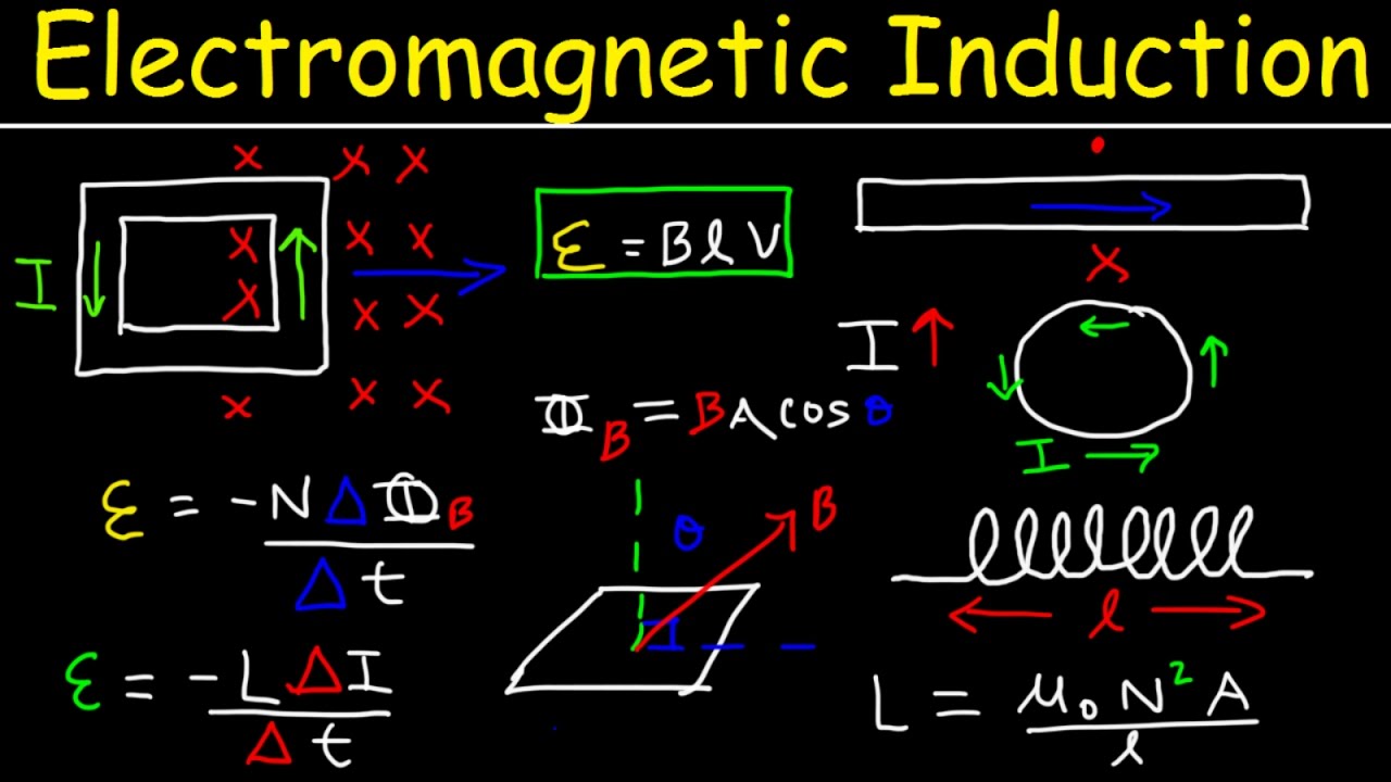
- Moving a magnet into or out of a coil of wire generates an electric current.
- The direction of the induced current reverses when the magnet's motion reverses.
- The magnitude of the induced current depends on the speed of the magnet's movement; faster movement induces a larger current.
- Current can also be induced by changing the coil's area, orientation (angle), or the magnetic field strength.
- Magnetic flux is the measure of the total magnetic field passing through a given area.
- Magnetic flux is calculated as the product of magnetic field strength (B), area (A), and the cosine of the angle (θ) between the magnetic field and the normal to the area (Φ = B * A * cos(θ)).
- The unit of magnetic flux is the Weber (Wb).
- Faraday's Law states that the induced EMF in a coil is proportional to the rate of change of magnetic flux through it (EMF = -N * ΔΦ/Δt).
- An induced EMF (and thus current, if the circuit is closed) is generated only when there is a change in magnetic flux.
- Lenz's Law states that the direction of an induced current is always such that it opposes the change in magnetic flux that produced it.
- If the magnetic flux is increasing, the induced current creates a magnetic field that opposes this increase.
- If the magnetic flux is decreasing, the induced current creates a magnetic field that tries to support the original flux.
- The right-hand rule is used to determine the direction of the magnetic field produced by a current in a wire or coil.
- A conductor moving through a magnetic field can have an EMF induced across it.
- The magnitude of the induced EMF in a straight conductor moving perpendicularly through a magnetic field is given by EMF = B * L * v, where B is the magnetic field strength, L is the length of the conductor, and v is its velocity.
- This induced EMF can drive a current if the conductor is part of a closed circuit.
- The direction of the induced current in a moving rod can be determined using Lenz's Law and the right-hand rule.
- An AC generator produces an alternating EMF by rotating a coil in a magnetic field, following the equation EMF = NBAω sin(ωt).
- Transformers use electromagnetic induction to change AC voltage levels.
- A step-up transformer increases voltage and decreases current, while a step-down transformer decreases voltage and increases current.
- The voltage and current ratios in an ideal transformer are inversely proportional to the ratio of turns in the secondary (Ns) and primary (Np) coils: Ns/Np = Vs/Vp = Ip/Is.
- Inductance (L) is a property of a coil that opposes changes in current flowing through it.
- The induced EMF in an inductor is given by EMF = -L * (ΔI/Δt).
- The inductance of a solenoid depends on its geometry (number of turns, length, area) and the permeability of its core material.
- Energy is stored in the magnetic field of an inductor, calculated as U = ½ * L * I².
Key takeaways
- Changing magnetic flux through a coil is the fundamental cause of induced electromotive force (EMF).
- Faraday's Law quantifies the induced EMF based on the rate of change of magnetic flux.
- Lenz's Law dictates that induced currents always oppose the change in flux that creates them, providing the direction.
- The magnitude of induced EMF depends on the strength of the magnetic field, the area of the coil, the number of turns, and how quickly these factors change.
- AC generators convert mechanical energy into electrical energy by rotating coils in magnetic fields.
- Transformers efficiently change AC voltage levels using mutual induction between two coils, crucial for power transmission.
- Inductors store energy in their magnetic fields and resist changes in current.
Key terms
Test your understanding
- How does changing the magnetic field strength, the area of a coil, or the angle between them affect magnetic flux?
- Explain Lenz's Law and how it determines the direction of an induced current.
- What is the relationship between the rate of change of magnetic flux and the induced EMF according to Faraday's Law?
- How do transformers use the principles of electromagnetic induction to change voltage levels?
- What factors determine the inductance of a solenoid, and how is energy stored in an inductor?