11:05
Understanding the Area Moment of Inertia
The Efficient Engineer
Overview
This video explains the concept of the area moment of inertia, a crucial property in engineering that quantifies a cross-section's resistance to bending. It details how the distribution of material relative to a bending axis significantly impacts stiffness. The video covers calculating the area moment of inertia using integration, provides formulas for common shapes, and introduces the parallel axis theorem for non-centroidal axes. It also touches upon composite shapes, flexural rigidity, radius of gyration, polar moment of inertia for torsion, and axis rotation using transformation equations and Mohr's circle.
How was this?
Save this permanently with flashcards, quizzes, and AI chat
Chapters
- The area moment of inertia measures a cross-section's resistance to bending.
- Material located further from the bending axis increases stiffness.
- Cross-sectional shape and material distribution are more important than total area for bending resistance.
- Efficient shapes like I-beams maximize material distance from the bending axis.
Understanding how material distribution affects bending resistance is fundamental to designing structures and components that can withstand applied loads without excessive deformation.
A plank of wood used to cross a canal is stiffer when oriented with its wider side parallel to the load, demonstrating how orientation affects bending resistance.
- The area moment of inertia is dependent on the chosen reference axis.
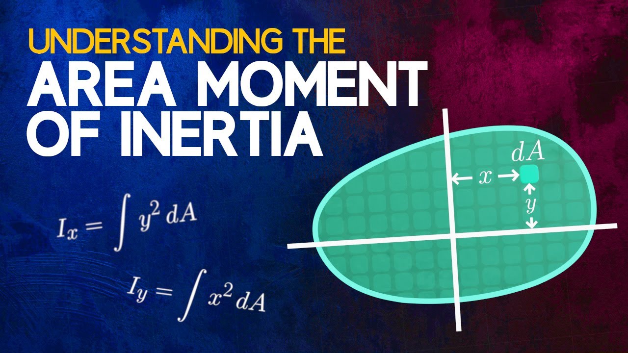
- It can be approximated by dividing the cross-section into small elements (dA) and summing their contribution (dA * Y^2).
- Integration provides a precise method for calculating the area moment of inertia (I-X, I-Y).
- The units are length to the fourth power (e.g., m^4), and the value is always positive due to the squared distance term.
Knowing how to calculate the area moment of inertia allows engineers to quantitatively predict how a specific shape will behave under bending stress.
Calculating I-X for a rectangle of width 'b' and height 'h' results in (b * h^3) / 12, showing a direct formula derived from integration.
- Reference texts provide pre-calculated area moment of inertia formulas for common shapes.
- These formulas are typically for centroidal axes, which pass through the cross-section's geometric center (centroid).
- The centroid is the geometric center of a cross-section.
Utilizing readily available formulas for standard shapes and centroidal axes simplifies calculations for common engineering scenarios.
Formulas for shapes like rectangles and circles about their centroidal axes are often found in engineering handbooks.
- The parallel axis theorem allows calculation of the area moment of inertia about any axis parallel to a centroidal axis.
- The formula is I = I_centroidal + A * d^2, where 'A' is the cross-sectional area and 'd' is the distance between the axes.
- This theorem is essential for calculating the moment of inertia of composite shapes or for axes not passing through the centroid.
This theorem extends the usefulness of standard formulas, enabling the analysis of complex or non-standard geometries by relating them back to known centroidal properties.
To find the moment of inertia of a rectangle about its bottom edge, you add the centroidal moment of inertia to the product of the rectangle's area and the squared distance from the centroid to the bottom edge.
- The area moments of inertia of simple shapes can be added or subtracted to find the moment of inertia of composite shapes.
- When combining shapes, ensure the parallel axis theorem is used if the reference axis doesn't align with each component's centroidal axis.
- Flexural rigidity (E*I) combines material stiffness (E, Young's modulus) and geometric resistance (I) to quantify a beam's resistance to bending.
- This property is critical in beam deflection and column buckling analysis.
Engineers frequently work with complex shapes; understanding how to combine simpler geometries and incorporating material properties allows for accurate prediction of structural behavior.
Calculating the moment of inertia for a T-beam by treating it as two rectangles and applying the parallel axis theorem to each component relative to a common reference axis.
- The polar moment of inertia (J) measures resistance to twisting (torsion) about an axis perpendicular to the cross-section.
- It is the sum of the area moments of inertia about two perpendicular axes (J = I-X + I-Y), according to the perpendicular axis theorem.
- Area moments of inertia are tensor quantities, meaning their values change with the orientation of the reference axes.
- Transformation equations and Mohr's circle can be used to find moments of inertia for rotated axes and identify principal moments (maximum and minimum values).
These concepts extend the analysis to torsional loads and provide a complete picture of a cross-section's resistance to bending and twisting in any orientation.
Using Mohr's circle, similar to stress transformation, to find the maximum and minimum area moments of inertia for a cross-section when the reference axes are rotated.
Key takeaways
- The area moment of inertia quantifies how effectively a cross-section resists bending based on its shape and material distribution.
- Material placed farther from the bending axis significantly increases stiffness.
- The area moment of inertia is axis-dependent; calculations must specify the reference axis.
- The parallel axis theorem is a powerful tool for calculating the moment of inertia for any axis parallel to a centroidal axis, especially for composite shapes.
- Flexural rigidity (E*I) combines material properties and geometric properties to define a beam's resistance to bending.
- The polar moment of inertia (J) is used to analyze resistance to torsional loads.
- Area moments of inertia, like stress, behave as tensors and can be analyzed for rotated axes using transformation equations or Mohr's circle.
Key terms
Area Moment of InertiaSecond Moment of AreaBending ResistanceCentroidCentroidal AxisParallel Axis TheoremComposite ShapeFlexural RigidityYoung's ModulusPolar Moment of InertiaPerpendicular Axis TheoremProduct of InertiaTensor Quantity
Test your understanding
- How does the distribution of material within a cross-section influence its resistance to bending, and why?
- What is the significance of the reference axis when calculating the area moment of inertia, and how does it affect the value?
- Explain the parallel axis theorem and describe a scenario where it would be essential for calculating the area moment of inertia.
- How does flexural rigidity (E*I) represent the combined resistance of a beam to bending, and what are its components?
- What is the difference between the area moment of inertia and the polar moment of inertia, and what types of loads does each relate to?